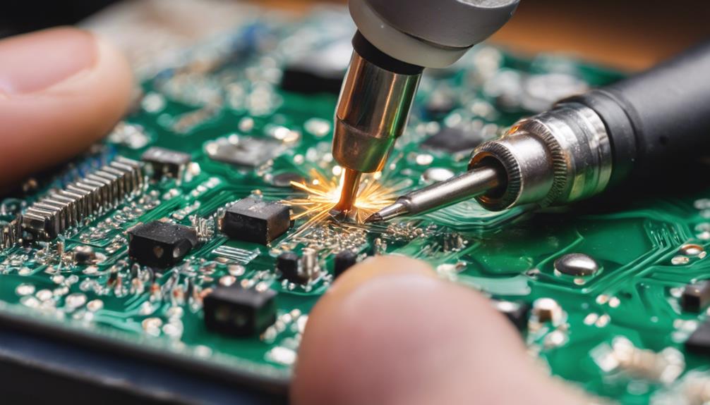
Through-hole component soldering requires precision and attention to detail. Mastering seven essential techniques is vital to achieving reliable and efficient solder joints. Temperature management is key, with precise temperature control preventing overheating and cold joints. Effective flux application, proper component placement, and solder wicking for desoldering are also essential. Preheating for best solder flow, preventing solder runoff, and inspecting for errors complete the list of critical techniques. By understanding these techniques, manufacturers can guarantee reliable and efficient solder joints, and maximize the full potential of through-hole component soldering.
Key Takeaways
- Maintain a consistent soldering iron temperature between 315°C to 427°C to prevent overheating and cold joints.
- Apply flux precisely using pens or brushes to enhance solder flow and wetting on component leads.
- Ensure proper component placement with adequate spacing for easy manual soldering and clean joints.
- Use preheating to minimize thermal shock and facilitate ideal solder flow, reducing defects and protecting sensitive components.
- Inspect regularly to prevent shorts, weak joints, and malfunctions, and to identify and correct errors for reliable circuit performance.
Mastering Soldering Iron Temperature
Mastering the essential temperature of the soldering iron is a vital step in achieving reliable and strong through-hole solder joints, as it directly impacts the quality of the bond and the integrity of the components.
The ideal temperature range for through-hole soldering iron tips typically falls between 315°C to 371°C (600°F to 700°F) for leaded solder and 371°C to 427°C (700°F to 800°F) for lead-free solder.
Maintaining a consistent soldering iron temperature is critical to prevent overheating, component damage, or cold solder joints. Temperature control stations offer precise adjustments for different components, ensuring excellent soldering results and preventing thermal damage.
Soldering iron tips with temperature control can enhance efficiency by allowing quick adjustments based on component size and heat requirements. Proper soldering iron temperature management is key to achieving reliable and strong through-hole solder joints, reducing the risk of defects or failures.
Effective Flux Application Methods
Proper flux application is an essential step in achieving reliable and strong through-hole solder joints, as it greatly enhances solder flow and wetting on component leads.
Effective flux application guarantees clean and reliable solder joints on through-hole components. When applying flux, it is important to do so sparingly to prevent excess residue buildup on the printed circuit board (PCB).
A flux pen or brush is ideal for precise application on component leads before soldering. Flux plays a critical role in removing oxides, improving solder adhesion, and reducing surface tension. This results in stronger and more dependable solder joints.
By using the correct flux application method, technicians can ensure that solder flows smoothly and evenly, resulting in robust and reliable through-hole solder joints.
Component Placement Best Practices
Effective flux application sets the stage for reliable through-hole solder joints, and equally important is the strategic placement of components on the printed circuit board (PCB) to guarantee excellent soldering results. Component placement best practices have a notable impact on the quality of through-hole solder joints. Adequate spacing between components ensures easier manual soldering and reduces the risk of solder bridges.
| Component Placement Considerations | Best Practices |
|---|---|
| Spacing between components | Maintain sufficient spacing for easy manual soldering |
| Placement of small surface mount parts | Place perpendicular to wave direction for efficient wave soldering |
| Thermal balance for small parts | Ensure proper thermal balance to prevent overheating or damage |
Collaboration with a PCB contract manufacturer can help optimize component placement for efficient through-hole soldering processes. Proper component placement enhances solder joint quality and overall PCB reliability. Ensure clean and properly aligned component placement to guarantee excellent soldering results. By following these best practices, manufacturers can achieve high-quality through-hole solder joints and reliable PCB performance.
Solder Wicking for Efficient Desoldering
The judicious use of solder wicking, a technique that leverages capillary action to remove excess solder, can greatly streamline the desoldering process and facilitate the efficient removal or replacement of through-hole components.
Solder wicking, also known as desoldering braid, is a copper braid coated with flux used to remove excess solder. The braid is placed on the solder joint, heated with a soldering iron to melt the solder, and then absorbs the molten solder. This process is effective for cleaning excess solder from through-hole components and PCBs, allowing for component removal or replacement.
Some key benefits of solder wicking include:
- Efficient removal of excess solder
- Enables efficient component removal or replacement
- Effective for cleaning PCBs and through-hole components
- Quick and efficient desoldering process with proper technique and quality desoldering braid
Preheating for Optimal Solder Flow
By preheating the PCB to a temperature of around 100-150°C, thermal shock to components is minimized, and ideal solder flow is facilitated. This essential step in soldering through-hole components ensures that sensitive components are protected from damage.
Preheating the PCB helps to achieve consistent soldering results, particularly for large or multilayer PCBs, by minimizing the temperature gradient across the board. This uniform heating during soldering reduces the risk of cold joints and thermal stress on the circuit board.
By preheating, the components are brought to a stable temperature, allowing for efficient solder flow and reducing the likelihood of defects. This technique is especially important for complex PCBs where temperature variations can have significant consequences.
Alternative Desoldering Techniques Explored

In the domain of alternative desoldering techniques, the choice of desoldering tools and heat gun techniques play a vital role in achieving efficient component removal.
This section will examine the various tools and methods utilized in desoldering, including specialized tools like the Hakko FR-301 and hot air guns, which enable effective removal of excess solder.
Desoldering Tools Used
Desoldering tools, whether traditional or alternative, play a crucial role in efficiently removing solder from through-hole component leads. The selection of the right desoldering tool can have a substantial impact on the effectiveness of the through-hole component rework process.
- Utilize specialized tools like the Hakko FR-301 desoldering tool for efficient desoldering of through-hole components.
- Consider using a blade soldering tip or pressing a round iron tip into solder wick for safe and effective desoldering.
- Alternative methods like using a small hand drill can offer quick and clean removal of solder from through-hole component leads.
- The blowing technique, involving blowing through a soda straw after applying heat and solder, can also effectively clear solder from PCB holes.
In through-hole technology, desoldering tools are essential for removing excess solder from through-hole parts during hole soldering and hand soldering processes. By employing the right desoldering tools and techniques, professionals can ensure efficient and reliable through-hole component rework.
Heat Gun Techniques
One effective alternative to traditional desoldering methods is the strategic application of heat gun techniques, which can efficiently remove excess solder from through-hole components. This approach offers a quick and efficient way to clean holes without relying on desoldering braid or solder suckers.
The heat gun method involves applying controlled heat to the solder joint, allowing the solder to melt and be easily removed. This technique is particularly effective for through-hole components with stubborn or excessive solder. By directing the heat gun's airflow on the solder joint, the solder liquefies and can be easily blown or wicked away for clean desoldering.
To achieve optimal results, it is essential to practice and control the heat gun temperature. A well-controlled temperature ensures that the solder melts efficiently, making it easier to remove. By mastering heat gun techniques, electronics enthusiasts and professionals can streamline their desoldering process, saving time and improving overall through-hole component soldering techniques.
What Soldering Techniques Are Recommended for SMT Component Placement Machines?
When it comes to SMT component placement machines, it’s crucial to use top smt component placement machine makers for best results. Selective soldering and reflow soldering are recommended techniques for accurate and efficient placement of components on PCBs. These methods ensure high-quality solder joints and reliable electrical connections.
Minimizing Solder Bridges and Errors

When it comes to minimizing solder bridges and errors, attention to detail is essential. By adopting a combination of preventive measures and thorough inspection, soldering defects can be greatly reduced.
In the following section, we will discuss key strategies for preventing solder runoff and inspecting for errors, ensuring reliable and efficient through-hole component soldering.
Prevent Solder Runoff
Proper control of the soldering process is essential to preventing solder runoff, a common issue that can lead to solder bridges and errors in through-hole component soldering. By adopting a few best practices, you can minimize the risk of solder runoff and guarantee reliable connections between through-hole components.
To prevent solder runoff, follow these guidelines:
- Use a controlled solder amount to avoid excess solder that can flow onto adjacent components.
- Confirm clean metal surfaces before soldering to promote proper solder flow and prevent errors.
- Maintain adequate cooling time to prevent solder from flowing excessively.
- Employ proper soldering technique, using quality soldering tools and materials to guarantee strong, reliable joints.
Inspect for Errors
Effective quality control during through-hole soldering relies on meticulous inspection for errors, as undetected solder bridges and weak joints can culminate in circuit malfunctions and failures. It is vital to inspect solder joints for potential errors like solder bridges that can cause short circuits between components. Using a magnifying glass or inspection tool, identify any soldering errors and guarantee proper connection between leads and PCB pads.
| Error Type | Description |
|---|---|
| Solder Bridges | Short circuits between components |
| Weak Connections | Incomplete or cold solder joints |
| Insufficient Solder | Inadequate solder to fill the hole |
| Excess Solder | Solder spreading between adjacent pads |
| Poor Fillet Formation | Weak joints leading to circuit failures |
Regular inspection for errors during through-hole soldering can prevent common issues like shorts, weak joints, and circuit malfunctions. By minimizing solder bridges and ensuring proper connections, you can assure reliable and efficient circuit performance. Remember, a thorough inspection is key to identifying and correcting errors, ensuring the quality and reliability of your through-hole soldering work.
Frequently Asked Questions
How to Solder Through-Hole Component?
Did you know that 75% of electronic failures are attributed to poor soldering techniques?
To effectively solder through-hole components, insert the lead through the PCB hole, ensuring a flush fit. Apply heat to the joint with a soldering iron, followed by solder application, allowing it to flow and form a solid connection. Hold the solder in place until it cools, creating a reliable fillet around the lead.
What Is the Best Solder Tip for Through-Hole Soldering?
When selecting a solder tip for through-hole soldering, a chisel tip is the best choice. Its flat edge provides a larger surface area for efficient heat transfer to component leads and PCB pads. This design enables precise soldering on small components and effective heat transfer on larger through-hole parts, resulting in consistent soldering results.
The chisel tip's stable temperature control and versatility make it an ideal solution for through-hole soldering applications.
What Are the General Requirements for Through-Hole Soldering?
For successful through-hole soldering, several key requirements must be met.
First, the printed circuit board (PCB) must have properly drilled and plated-through holes to guarantee reliable electrical connections. Components with leads of suitable diameter and material must be selected. A suitable solder alloy with adequate melting point and flux must be chosen.
Additionally, a clean and temperature-controlled soldering environment is vital. Finally, the operator must possess adequate soldering skills and follow established techniques to achieve strong, reliable joints.
What Is the Name of the Through-Hole Soldering?
The age-old question that has plagued engineers for decades: what is the name of this revered technique? Allow me to enlighten you – it's none other than Through-Hole Soldering (THS).
This stalwart method has been the backbone of electronic assembly since the 1950s, providing unwavering reliability in high-stress environments. By inserting component leads into plated-through holes, THS guarantees robust electrical and mechanical connections, making it an indispensable tool in the world of electronics.