When designing aerospace PCBs, the substrate material selection is critical for reliable operation in extreme temperatures ranging from -55°C to 125°C. Key factors to take into account include high thermal conductivity, low outgassing, high dielectric strength, and mechanical strength. Materials like aluminum nitride and PTFE offer exceptional thermal conductivity and low dielectric constants, while polyimide and Rogers materials provide excellent electrical properties and mechanical strength. By understanding the specific requirements for aerospace PCBs, designers can make informed decisions about substrate materials, ensuring top performance, reliability, and durability. Further exploration of the unique demands of aerospace applications reveals a nuanced understanding of substrate material selection.
Key Takeaways
- Aerospace PCB substrates must withstand extreme temperatures (-55°C to 125°C) and require high thermal conductivity materials like aluminum nitride.
- Materials with low outgassing properties, like PTFE, prevent contamination in space environments and ensure signal integrity.
- Selecting materials with high thermal stability, low coefficient of thermal expansion, and high dielectric strength is crucial for reliable operation.
- Balancing signal performance with mechanical and thermal considerations is vital, and materials like polyimide and PTFE offer excellent electrical and thermal properties.
- Rogers materials and high-frequency laminates provide exceptional signal integrity and reliability in extreme environments, making them ideal for aerospace PCBs.
Factors in Aerospace PCB Substrates
A critical consideration in the selection of aerospace PCB substrates is the importance of withstanding extreme temperatures, as avionics applications require operation across a broad thermal range of -55°C to 125°C. This demands the use of materials with high thermal conductivity, such as aluminum nitride, to efficiently dissipate heat generated by electronic components.
Additionally, aerospace PCB substrates must exhibit low outgassing properties to prevent contamination in space environments, guaranteeing the reliability of critical systems. The selection of materials with high dielectric strength, like PTFE, is also essential to ensure the integrity of electrical signals in harsh aerospace environments.
Moreover, aerospace PCB substrates must meet stringent quality and reliability standards to guarantee safe and reliable operation in aircraft systems. By carefully considering these factors in substrate selection, engineers can develop aerospace PCBs that meet the demanding requirements of avionics applications.
Thermal Stability for High-Temperature

The thermal stability of aerospace PCB substrates is a critical factor in ensuring the reliable operation of electronic components in high-temperature environments, where even slight deviations in thermal expansion can lead to catastrophic failures.
In space environments, aerospace PCBs are exposed to extreme temperatures, making it essential to select substrate materials with high thermal stability. A low coefficient of thermal expansion is vital to prevent warping or delamination under thermal stress, ensuring the integrity of the PCB.
High-temperature substrate materials like Aluminum Nitride or Beryllium Oxide offer exceptional thermal conductivity, up to 170W/mK, for efficient heat dissipation in aerospace applications.
Low Dielectric Constant Materials

When choosing low dielectric constant materials for aerospace PCBs, it is vital to take into account the trade-offs between material properties, signal speed, and loss.
The selection of material will affect signal integrity, thermal management, and overall system performance.
Material Property Trade-Offs
Balancing signal performance with mechanical and thermal considerations is essential when selecting low dielectric constant materials for aerospace PCBs. This delicate balance is vital to guarantee the peak functioning of high-frequency applications in aerospace electronics.
Low dielectric constant materials offer superior electrical properties, making them ideal for high-frequency applications. They provide reduced signal delay, improved impedance control, and enhanced signal integrity by minimizing signal distortion and loss.
However, selecting these materials involves trade-offs between signal performance, mechanical properties, and thermal considerations. For instance, a material with excellent electrical properties may compromise on mechanical strength or thermal stability. Conversely, a material with superior mechanical properties may sacrifice some electrical performance.
Aerospace PCB designers must carefully weigh these material property trade-offs to achieve the best balance for their specific application. By understanding these trade-offs, designers can select the most suitable low dielectric constant material for their aerospace PCBs, ensuring reliable and high-performance operation in demanding aerospace environments.
Signal Speed and Loss
In high-frequency aerospace applications, signal speed and loss become critical considerations, as even slight signal degradation can compromise system performance and reliability. To mitigate this, low dielectric constant materials are essential in aerospace PCBs. These materials, such as PTFE, minimize signal reflections and crosstalk, enhancing overall signal quality.
| Material | Dielectric Constant |
|---|---|
| PTFE | 2.1 |
| FR4 | 4.3 |
| Polyimide | 3.5 |
| Ceramic | 5.5 |
| Glass Epoxy | 6.1 |
The choice of substrate with low dielectric constant directly impacts the performance and reliability of high-speed data transmission in aerospace systems. By selecting materials with low dielectric constants, signal loss and degradation are notably reduced, ensuring efficient signal propagation and data transfer at high frequencies. This is particularly vital in aerospace PCBs, where signal integrity is paramount. By understanding the importance of low dielectric constant materials, designers and engineers can optimize their substrate selection to guarantee the highest level of performance and reliability in their aerospace systems.
Thermal Management Options
Beyond signal integrity, the thermal management capabilities of low dielectric constant materials play an essential role in aerospace PCBs, where excessive heat can compromise component reliability and overall system performance. As aerospace electronics operate in high-frequency applications, low dielectric constant materials are vital for efficient thermal management. These materials, with a dielectric constant typically below 3, guarantee minimal signal loss and interference, thereby maintaining signal integrity and preventing impedance mismatch.
Key benefits of low dielectric constant materials for thermal management in aerospace PCBs include:
- Efficient heat dissipation: Low dielectric constant materials facilitate efficient heat dissipation, reducing the risk of component failure and system downtime.
- High-performance operation: By minimizing signal loss and interference, low dielectric constant materials enable high-performance operation in demanding aerospace applications.
- Reliability and durability: The use of low dielectric constant materials enhances the overall reliability and durability of aerospace PCBs, ensuring consistent performance in harsh environments.
Mechanical Strength and Durability

Aerospace PCB substrate materials must exhibit exceptional mechanical strength and durability to withstand the extreme conditions and harsh environments encountered during flight. High mechanical strength is essential to guarantee the reliability and performance of aerospace PCBs, which are subjected to vibrations, shocks, and extreme temperatures.
Materials such as Rogers RO3003 and RO4003 provide excellent mechanical properties, making them suitable for aerospace PCB applications. The high flexural strength of materials like PTFE and Polyimide is necessary for withstanding the mechanical stresses encountered during flight.
Durability is also vital, as aerospace PCBs must operate reliably over an extended period in harsh environments.
The selection of substrate materials for aerospace PCBs must be done carefully to meet stringent industry standards for mechanical performance. By choosing materials with high mechanical strength and durability, designers can secure the reliability and performance of aerospace PCBs, even in the most demanding environments.
Polyimide Substrate Material Properties

Polyimide substrate materials, renowned for their exceptional mechanical strength and durability, also boast a unique set of properties that make them an attractive option for aerospace PCB applications. These properties, combined with their robust nature, make polyimide substrates an ideal choice for demanding aerospace environments.
Here are three key properties that highlight the suitability of polyimide substrates for aerospace PCBs:
- Electrical Properties: Polyimide substrates offer excellent electrical properties, making them ideal for aerospace PCBs where signal integrity is paramount.
- High Resistance: These substrates exhibit high resistance to heat and chemicals, essential for demanding aerospace applications where exposure to extreme temperatures and harsh chemicals is common.
- Chemical Resistance: Polyimide materials are highly resistant to chemicals, ensuring that they can withstand the harsh conditions often encountered in aerospace environments.
The combination of these properties, along with their mechanical strength and durability, makes polyimide substrates an attractive option for aerospace PCB applications. Their robust nature and versatility in design and functionality make them an ideal choice for a range of aerospace applications.
PTFE Substrate Benefits and Drawbacks

In high-frequency and microwave applications, PTFE substrates offer a unique combination of thermal and electrical properties that make them an attractive option for aerospace PCB designs. The excellent thermal characteristics of PTFE substrates make them ideal for high-frequency and microwave applications, providing efficient heat dissipation and reduced thermal stress.
Additionally, PTFE substrates have low dielectric constants, which enable efficient signal transmission and reduced signal loss, making them suitable for aerospace applications. Moreover, PTFE substrates are chemically inert, ensuring resistance to harsh environments and chemicals commonly encountered in aerospace applications. This property, combined with their lightweight and durable nature, contributes to weight reduction and enhanced performance in aerospace PCB assemblies.
However, the higher cost of PTFE substrates compared to traditional materials like FR-4 can impact overall PCB manufacturing expenses. Despite this drawback, the benefits of PTFE substrates make them a valuable option for aerospace PCB designs where high-frequency performance and reliability are critical.
FR-4 and CEM-1 Material Comparison
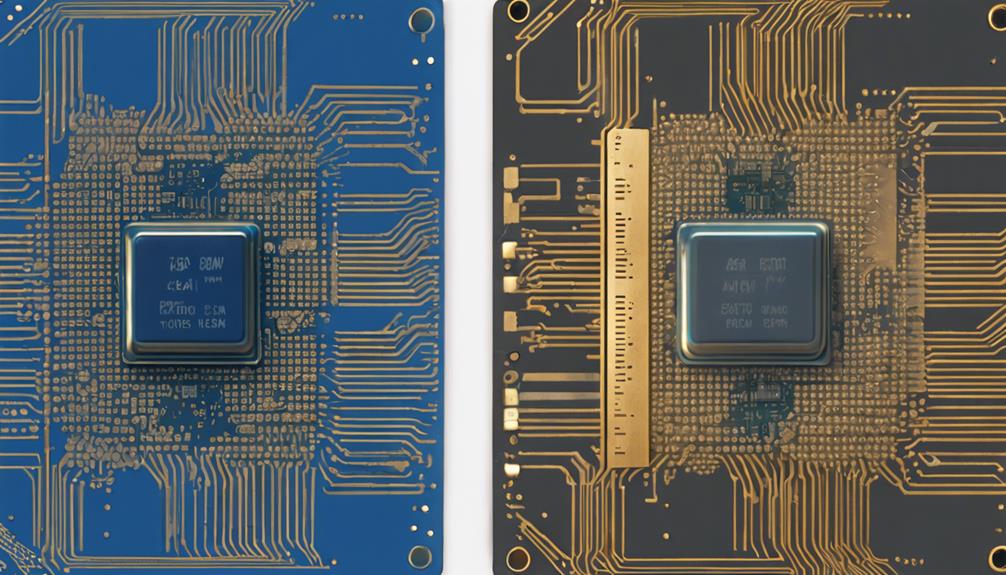
When evaluating FR-4 and CEM-1 for aerospace PCB applications, a thorough examination of their material properties is essential.
A comparison of their thermal resistance, moisture absorption rates, and other key characteristics will reveal the strengths and weaknesses of each material.
Material Properties Compared
Among substrate materials, a key consideration for aerospace PCBs is the comparison of FR-4 and CEM-1, two popular options that exhibit distinct properties. While both materials are widely used in aerospace applications, they differ in their electrical and mechanical properties.
When evaluating these materials, the following key differences emerge:
- Electrical Properties: FR-4 is known for its high Tg values, whereas CEM-1 offers superior electrical properties, making it a suitable alternative for high-reliability aerospace PCBs.
- Mechanical Properties: CEM-1 excels in flexural strength, handling physical stress well, and providing a cost-effective solution. In contrast, FR-4 boasts a wide temperature range and good strength-to-weight ratios.
- Cost and Versatility: FR-4 is a low-cost, versatile material, whereas CEM-1 provides a reliable, cost-effective alternative with specific advantages for aerospace PCBs.
Thermal Resistance Analysis
Thermal resistance analysis is a critical aspect of aerospace PCB design, and a comparison of FR-4 and CEM-1 materials reveals distinct differences in their thermal conductivity. FR-4 substrates, with a thermal conductivity of approximately 0.35 W/mK, are suitable for aerospace PCBs, but have limitations in managing thermal resistance.
In contrast, CEM-1 materials offer a higher thermal conductivity of around 0.5 W/mK, making them a more effective choice for heat dissipation in high-temperature aerospace applications.
The thermal resistance analysis between FR-4 and CEM-1 highlights the importance of selecting the right substrate for aerospace PCBs to secure optimal performance under high temperature conditions. While FR-4 materials are cost-effective, their thermal conductivity limitations may compromise the reliability and performance of aerospace PCBs.
In contrast, CEM-1 materials provide better heat dissipation capabilities, making them a more suitable choice for aerospace applications where thermal resistance is a critical factor. By understanding the thermal conductivity differences between FR-4 and CEM-1, designers can make informed decisions when selecting substrate materials for aerospace PCBs.
Moisture Absorption Rates
In aerospace PCB design, substrate materials' moisture absorption rates greatly impact their reliability and electrical performance under varying environmental conditions. The selection of substrate materials with suitable moisture absorption rates is vital to guarantee the long-term stability of aerospace PCBs.
When comparing FR-4 and CEM-1 materials, significant differences in moisture absorption rates are observed. FR-4 materials exhibit a moisture absorption rate of around 0.15% to 0.25%, making them suitable for aerospace applications where reliability is paramount. In contrast, CEM-1 materials have a higher moisture absorption rate ranging from 0.4% to 0.8%, which can impact their performance in aerospace applications.
Key differences in moisture absorption rates:
- FR-4: 0.15% to 0.25%
- CEM-1: 0.4% to 0.8%
- Lower moisture absorption rates in FR-4 contribute to their widespread use in aerospace applications.
Understanding the moisture absorption rates of substrate materials is essential for designing aerospace PCBs with long-term stability. By selecting materials with appropriate moisture absorption rates, designers can secure the reliability and electrical performance of aerospace PCBs under varying environmental conditions.
High-Frequency Laminates for Aerospace
High-frequency laminates play a vital role in aerospace PCBs, as they provide exceptional signal integrity and reliability in extreme environments, making them an essential component in modern aerospace systems.
These laminates are specifically designed to operate at frequencies above 1 GHz, ensuring excellent signal integrity and reliability in aerospace applications.
The low dielectric constant and loss tangent of high-frequency materials, such as PTFE-based laminates, enable high-speed data transmission with minimal signal degradation. Additionally, these materials demonstrate exceptional thermal stability, ensuring reliable operation in extreme aerospace environments.
Precise impedance control is also critical in RF and microwave circuit performance, and high-frequency laminates ensure this requirement is met.
The selection of high-frequency laminates is important in meeting stringent aerospace industry standards for signal integrity and reliability.
Metal Core PCB Materials for Thermal

Beyond signal integrity, the aerospace industry's stringent thermal management requirements necessitate the use of metal core PCB materials, which excel in heat dissipation due to their high thermal conductivity. This is particularly important in aerospace applications where heat buildup can compromise the reliability of electronic components.
Metal core PCB materials are specifically designed to efficiently dissipate heat generated by components in aerospace electronic systems.
Here are three key benefits of using metal core PCB materials:
- High thermal conductivity: Metal core PCB materials, such as aluminum and copper, possess high thermal conductivity, ensuring efficient heat transfer in aerospace systems.
- Reliable heat dissipation: The metal core in PCB materials helps to efficiently dissipate heat, improving overall reliability and longevity of electronic components.
- Enhanced performance: By effectively managing heat, metal core PCB materials enable aerospace electronic systems to operate at peak levels, ensuring top performance and reliability.
Rogers Material for High-Performance
Rogers material, a woven glass-reinforced hydrocarbon composite, is a preferred substrate material in aerospace PCBs, offering exceptional electrical performance and reliability in demanding environments. Its unique composition makes it an ideal choice for high-performance aerospace applications, where signal integrity and low loss properties are vital. Rogers material provides high frequency stability, guaranteeing reliable communication and data transmission in aerospace electronic systems.
Aerospace engineers often prefer Rogers material for its high reliability, durability, and performance consistency in demanding environments. Its exceptional thermal management capabilities ensure effective heat dissipation, making it suitable for high-power aerospace applications.
With its superior signal integrity and low loss properties, Rogers material is a popular choice for aerospace PCBs requiring high-speed data transmission and reliable communication.
In high-performance aerospace PCBs, Rogers material's exceptional electrical performance and thermal management capabilities make it an ideal substrate material. Its reliability and durability in demanding environments make it a preferred choice for aerospace engineers, safeguarding the success of critical aerospace missions.
Polyimide and PTFE Material Comparison

In the field of aerospace PCBs, Polyimide and PTFE substrates emerge as two prominent contenders, each boasting unique strengths that cater to distinct design requirements. When selecting a substrate material, understanding the advantages of each is essential for peak performance.
Here are key differences between Polyimide and PTFE substrates:
- Electrical Properties: Polyimide offers exceptional electrical properties and resistance to heat and chemicals, making it ideal for aerospace PCB applications.
- Thermal Characteristics: PTFE substrates excel in high-frequency applications, thanks to their low loss tangent and stable dielectric constant, making them suitable for high-performance aerospace PCBs.
- Flexibility and Strength: Polyimide substrates are commonly used in flexible PCBs due to their flexibility and resistance to warping, while PTFE substrates boast high physical strength.
The choice between Polyimide and PTFE substrates depends on the specific requirements of the aerospace PCB design, with each material offering unique benefits for high-performance applications. By understanding the strengths of each substrate material, designers can make informed decisions to guarantee peak performance in demanding aerospace environments.
Aerospace PCB Substrate Material Selection
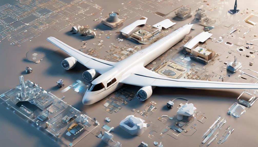
When selecting a substrate material for aerospace PCBs, designers must carefully consider the unique demands of this field, prioritizing materials that can withstand extreme temperatures, radiation, and vibration.
Aerospace PCBs require substrate materials with high thermal conductivity and excellent dielectric properties to withstand extreme operating conditions. Materials like Aluminum, Aluminum nitride, and Beryllium oxide are commonly used in aerospace PCBs for their high operating temperatures and low expansion coefficients.
The selection of substrate materials for aerospace PCBs is crucial in guaranteeing the reliability and performance of electronic components in aircraft and space vehicles. These materials must also exhibit strong dimensional stability and electrical properties to meet the stringent requirements of the aerospace industry.
The choice of substrate materials for aerospace PCBs plays an essential role in the overall functionality and longevity of electronic systems in aerospace applications. By carefully selecting the right substrate material, designers can secure the reliability and performance of aerospace PCBs, ultimately contributing to the success of critical aerospace missions.
Substrate Materials for High-Reliability

When selecting substrate materials for high-reliability aerospace PCBs, it is essential to contemplate the critical criteria that guarantee peak performance and durability.
The choice of substrate material greatly impacts thermal management, as aerospace applications often involve extreme temperatures and high-power densities.
Material Selection Criteria
Optimizing substrate material selection for aerospace PCBs necessitates a careful evaluation of thermal, mechanical, and electrical performance criteria to guarantee high-reliability operation in extreme environments.
Aerospace PCB material selection criteria prioritize high reliability, thermal stability, and mechanical strength to withstand harsh operating conditions. Substrate materials like Rogers RO4000 series are preferred for aerospace PCBs due to their dimensional stability, low loss, and high frequency performance.
High Tg values of substrate materials ensure stable performance in aerospace applications where temperature variations are extreme.
The following material selection criteria are essential for aerospace PCBs:
- High Tg values: Ensuring stable performance in extreme temperature variations.
- Low moisture absorption: Preventing performance degradation in high humidity environments.
- Mechanical strength: Withstanding mechanical stress and vibration in aerospace applications.
Thermal Management Options
Thermal management is a critical consideration in aerospace PCB design, as excessive heat buildup can lead to component failure and compromised system performance.
In high-reliability aerospace applications, substrate materials play a crucial role in thermal management. Materials like Aluminum, Aluminum Nitride, and Beryllium Oxide offer high thermal conductivity, guaranteeing effective heat dissipation and maintaining peak system performance.
These substrate materials can withstand high operating temperatures up to 350°C, making them ideal for aerospace applications. Additionally, their low expansion coefficients (around 4 ppm/°C) ensure dimensional stability under thermal stress, minimizing the risk of component failure.
The strong dielectric properties of these materials also enable efficient heat transfer, further enhancing system reliability.
Thermal Management in Aerospace PCBs
High-reliability aerospace applications necessitate stringent thermal management in printed circuit boards (PCBs) to guarantee the peak performance of electronic components in extreme temperature conditions. Effective thermal management is critical to prevent overheating, which can lead to component failure and system malfunction.
To achieve ideal thermal management in aerospace PCBs, substrate materials with high thermal conductivity are essential. These materials enable efficient heat dissipation, preventing thermal buildup and ensuring reliable operation of electronic components.
Key considerations for thermal management in aerospace PCBs include:
- Thermal conductivity: Substrate materials with high thermal conductivity, such as aluminum nitride and ceramic substrates, are ideal for aerospace PCBs.
- High temperature: Aerospace PCBs must be designed to operate reliably in extreme temperature conditions, making thermal management a top priority.
- Substrate material selection: Proper selection of substrate materials is crucial to guarantee efficient thermal management and reliable performance of electronic components in aerospace applications.
Material Properties for Aerospace Applications
Selecting substrate materials for aerospace PCBs necessitates a thorough examination of their material properties, as the optimal combination of thermal conductivity, dielectric characteristics, and mechanical strength is vital for reliable performance in extreme environments.
Aerospace PCB substrate materials require high thermal conductivity (up to 170W/mK) and excellent dielectric properties to guarantee efficient operation in extreme conditions. Operating temperatures can reach up to 350°C, requiring materials with low expansion coefficients (4 ppm/°C) to maintain stability. Materials like Aluminum, Aluminum nitride, and Beryllium oxide are commonly used in aerospace PCBs for their strength, thermal conductivity, and dielectric characteristics.
Flexible-rigid PCBs, combining flexible and rigid materials like RO3000 and RO4000, are utilized in aerospace applications for their lightweight and dimensional stability.
The selection of substrate materials for aerospace PCBs is essential to ensure reliability, performance, and durability in challenging environments like aircraft and space systems. By carefully evaluating material properties, engineers can design and develop aerospace PCBs that meet the demanding requirements of these applications.
Frequently Asked Questions
How Do You Select a PCB Substrate?
When selecting a PCB substrate, consider the operating environment and required performance. Assess the temperature range, moisture exposure, and mechanical stress the board will encounter.
Opt for materials with high thermal stability, low moisture absorption, and excellent mechanical strength. Prioritize substrates with high dielectric strength and glass shift temperatures (Tg) to guarantee reliable insulation and thermal stability.
What Material Is Commonly Used as the Substrate for Pcbs?
In the domain of printed circuit boards (PCBs), the most commonly used substrate material is FR4, a flame retardant epoxy glass substrate. Its widespread adoption is attributed to its affordability, versatility, and high Tg values.
FR4's balanced properties make it an ideal choice for various applications, offering a reliable and cost-effective solution for PCB manufacturing.
How Do You Choose a PCB Material?
'Measure twice, cut once' is a timeless adage that rings particularly true when selecting a PCB material. When choosing a PCB material, it is essential to take into account the operating temperature range, thermal conductivity, dielectric properties, weight, and dimensional stability.
Which Materials Are Used for Pcbs?
When selecting materials for printed circuit boards (PCBs), several options are available. FR4, CEM, Teflon, Polyimide, and Rogers are popular substrate materials used in PCB manufacturing.
Each material offers unique properties, such as temperature range, electrical characteristics, and chemical resistance. Understanding these properties is essential in choosing the best material for specific applications, ensuring reliable performance and durability in demanding environments.

