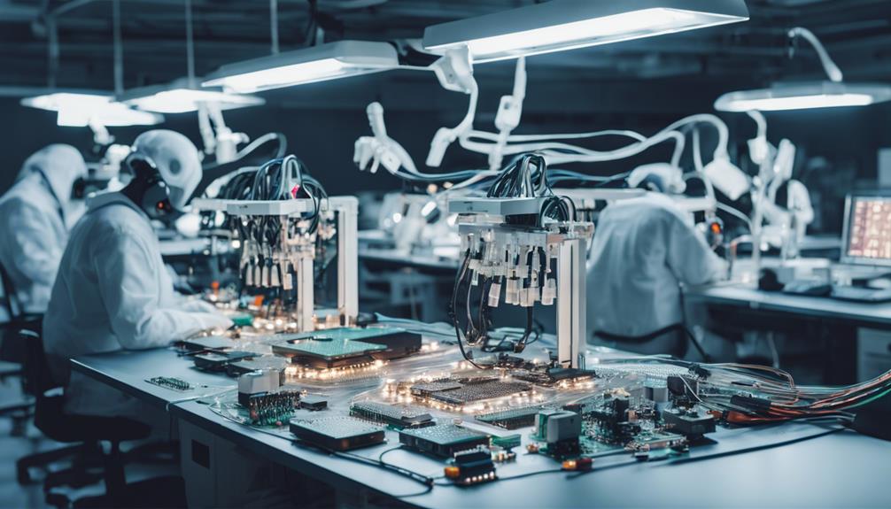
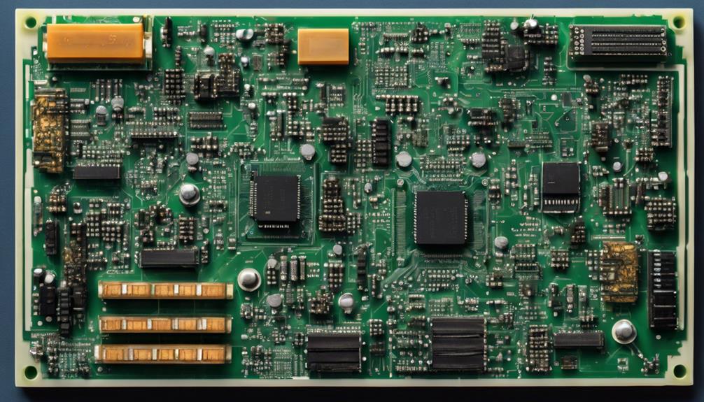
SMT component placement is a critical step in electronic device assembly, requiring precise orientation, spacing, and alignment to guarantee ideal functionality, reliability, and performance. Correct component orientation, ideal spacing, and accurate alignment methods are essential to prevent electrical interference, short circuits, and thermal issues. Advanced placement machines, automated systems, and design software tools aid in precise component placement, minimizing errors and reducing assembly time. By following a deliberate approach to SMT component placement, manufacturers can enhance process efficiency, reduce costs, and improve product quality, and uncovering the intricacies of this process can lead to even more significant benefits.
Key Takeaways
- Correct component orientation is crucial for circuit board functionality, considering pin 1, polarity markings, and alignment features.
- Optimal component spacing techniques prevent electrical interference, aid heat dissipation, and reduce short circuit risks.
- Accurate footprints with complete component data ensure precise component placement, preventing manufacturing defects.
- Advanced placement machines with vision systems and robotic arms optimize component placement, reducing errors and increasing efficiency.
- Strategic component placement strategies reduce signal interference, assembly errors, and improve yield rates, enhancing overall process efficiency.
SMT Component Orientation Essentials
Correct component orientation is consistently crucial in surface mount technology (SMT) assembly, as it directly impacts the functionality and reliability of the circuit board. Incorrect orientation can lead to circuit failure, short circuits, or improper functionality, underscoring the importance of accurate component orientation.
To guarantee proper placement, it is essential to identify pin 1, polarity markings, and alignment features on the component. Components such as diodes, ICs, and connectors have specific orientation requirements that must be followed.
Utilizing reference designators and datasheets ensures precise component orientation during placement. Pin 1 identification is crucial, as it determines the component's polarity and functionality. Polarity markings, such as a notch or dot, indicate the component's orientation. Alignment features, like a tab or notch, aid in correct placement.
Optimal Component Spacing Techniques

In addition to ensuring accurate component orientation, maintaining ideal spacing between components is essential for preventing electrical interference and ensuring proper heat dissipation in surface mount technology (SMT) assembly. Effective component spacing techniques play a significant role in ensuring the reliability and longevity of electronic systems.
Industry standards recommend minimum component spacing based on factors like component size, thermal considerations, and assembly requirements. Adequate spacing between components helps reduce the risk of short circuits and facilitates easier troubleshooting and maintenance. Proper component spacing also contributes to the overall reliability and longevity of the electronic system by mitigating potential performance issues.
To achieve ideal spacing, designers can utilize design software tools to determine the best component placement, ensuring that spacing requirements are met and assembly issues are avoided.
Some key considerations for ideal component spacing include:
- Maintaining a safe distance between components to prevent electrical interference
- Ensuring adequate thermal clearance for heat dissipation
- Facilitating easy maintenance and troubleshooting through accessible component placement
PCB Design for Efficient Placement
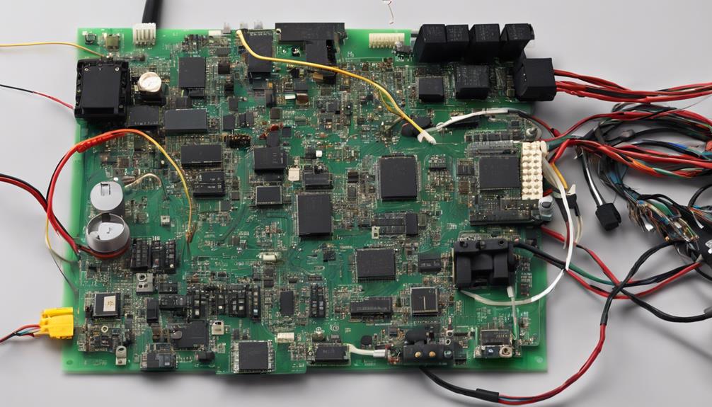
For ideal component placement, PCB design must meticulously account for the precise spatial relationships between components, taking into consideration factors such as footprint accuracy, pad sizes, and design rules.
Inaccurate footprints can lead to component placement tolerances issues, resulting in manufacturing defects. Hence, PCB design must guarantee that footprints accurately match component dimensions to prevent such issues.
Incorrect pad sizes or locations can result in weak solder joints during the placement process, emphasizing the importance of precise pad design. Additionally, design rules must be followed to maintain proper component spacing and prevent short circuits.
Footprints should be built to the maximum specified material width for efficient component placement. Including complete component data in footprints enables 3D checking and aids in mechanical design considerations for placement accuracy.
Component Placement Machines Overview
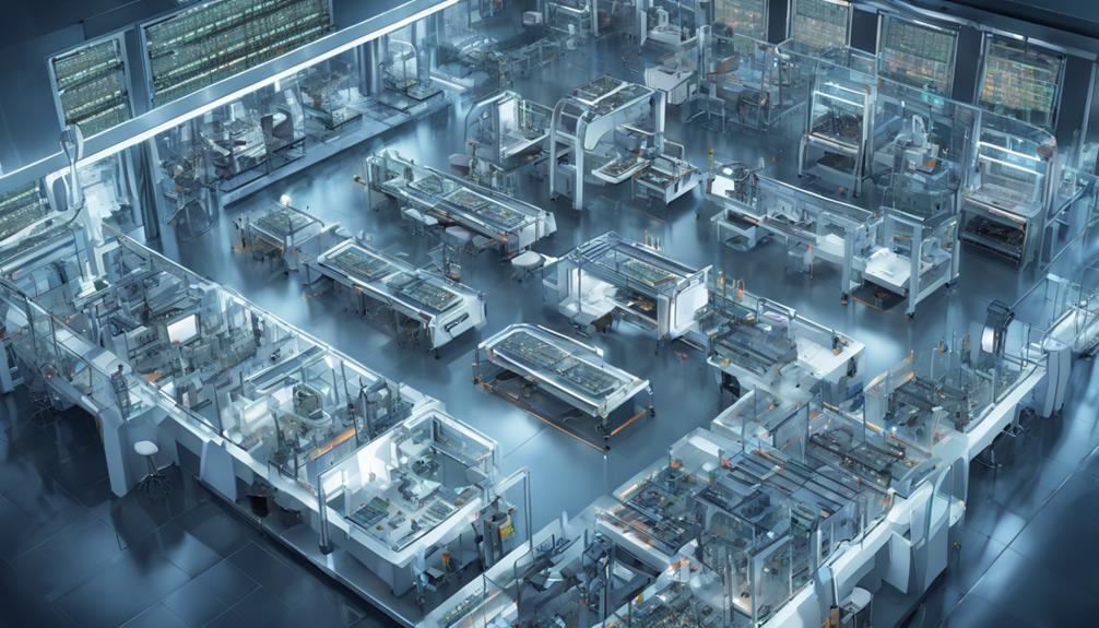
In the field of component placement machines, various types and classifications exist, each with its unique characteristics and capabilities.
The techniques employed by these machines, such as high-speed placement and precision vision systems, are critical to achieving accurate component placement.
Understanding the different machine types and placement techniques is essential for optimizing PCB assembly processes.
Machine Types and Classifications
Component placement machines are categorized into distinct types based on their placement speed, accuracy, and capabilities, each suited to specific assembly requirements and production volumes.
These machines can be classified into three primary categories:
- High-Speed Machines: Designed for high-volume production, these machines can place up to 100,000 components per hour with exceptional precision, making them ideal for large-scale assembly lines.
- Mid-Speed Machines: Offering a balance between speed and accuracy, these machines are suitable for a wide range of components and are commonly used in medium-volume production.
- Flexible Placement Machines: Equipped with advanced vision systems and software, these machines can handle various component sizes and types, adapting to diverse assembly needs and providing unparalleled flexibility.
These machine types cater to diverse production needs, ensuring accurate and efficient component placement. By selecting the right machine type, manufacturers can optimize their assembly processes, reduce errors, and increase productivity.
Component Placement Techniques
Through the integration of advanced technologies, component placement machines have evolved to facilitate precise and efficient placement of surface mount components on printed circuit boards. These machines, such as pick-and-place systems, automate the accurate positioning of components, ensuring reliable and high-quality production.
By leveraging vision systems and robotic arms, component placement machines can pick up components from reels or trays and place them onto designated locations on the board with precision.
Advanced placement machines offer a range of features that enhance production efficiency and accuracy. High-speed placement machines, for instance, can achieve placement rates of thousands of components per hour, making them ideal for high-volume production.
Furthermore, these machines can handle a wide range of component sizes and shapes, from small passive components to larger integrated circuits. Features like vision alignment, rotation capabilities, and multiple placement heads for diverse component types further optimize the placement of components.
Role of SMT Component Placement
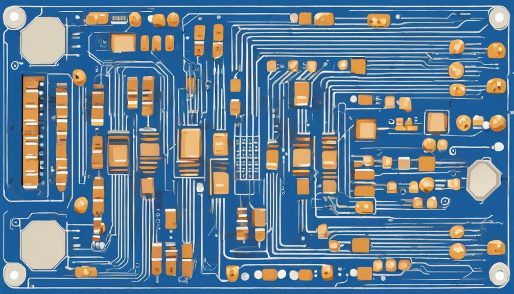
Accurate placement of surface-mount technology (SMT) components plays a pivotal role in ensuring the reliability and performance of the final product. In the domain of electronic devices, SMT component placement is a critical step in printed circuit board (PCB) assembly, where components are accurately positioned on the board. This process is essential for ensuring electrical connectivity, thermal management, and mechanical stability in the final product.
Proper SMT component placement is indispensable for:
- Ensuring electrical connectivity and preventing shorts or opens
- Maintaining thermal management and preventing overheating
- Providing mechanical stability and preventing component damage
As technological advancements continue to drive innovation in board assembly, the role of SMT component placement becomes even more essential. With advanced placement machines using vision systems and robotic arms to precisely position components on the PCB, manufacturers can optimize manufacturing efficiency and ensure that components on your board meet design specifications.
Accurate Component Alignment Methods
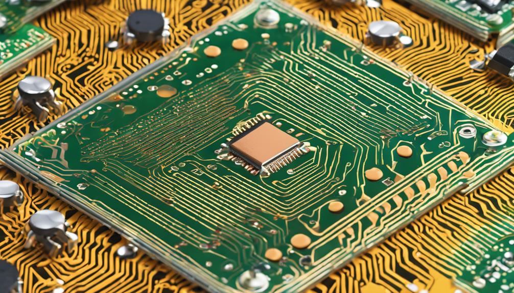
To guarantee precise surface-mount technology (SMT) component placement, manufacturers employ advanced alignment methods that leverage cutting-edge technologies to minimize errors and optimize the assembly process. Automated pick-and-place machines are utilized to achieve high-speed and accurate component alignment.
Vision systems are implemented to confirm correct component orientation and placement on the printed circuit board (PCB). Fiducial markers serve as alignment reference points during the component placement process, ensuring accurate registration and positioning.
Advanced software algorithms optimize component arrangement and minimize placement errors, while laser alignment systems fine-tune component positioning with exceptional precision. Additionally, Automated Optical Inspection (AOI) systems verify component placement and detect any defects or misalignments.
SMT Assembly Process Optimization
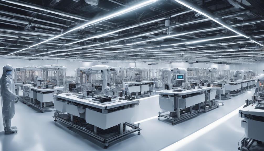
Improving the SMT assembly process is essential for efficient electronic board development. It begins with strategic component placement strategies that enhance process efficiency. By minimizing errors and reducing assembly time, manufacturers can improve overall product quality and increase manufacturing yield.
To achieve this, it is important to implement component placement strategies that prioritize process efficiency improvement, manufacturing time reduction, and ideal component positioning.
Process Efficiency Improvement
By streamlining the SMT assembly process through strategic component placement, manufacturers can achieve significant gains in productivity, quality, and cost savings. Optimizing the SMT assembly process is important for achieving operational efficiency, reducing costs, and improving product quality.
Proper component placement techniques play an important role in minimizing errors, preventing rework, and enhancing overall production yield. Implementing automated systems for component placement can greatly speed up the assembly process and guarantee accuracy.
Some key strategies for process efficiency improvement include:
- Implementing automated assembly systems to increase speed and accuracy
- Refining component placement techniques to minimize errors and rework
- Developing strategic component layout plans to streamline workflow and reduce assembly time
Component Placement Strategies
Effective component placement strategies in SMT assembly involve a deliberate and systematic approach to guarantee precise component orientation, spacing, and alignment, which are critical to achieving high-quality solder joints and reliable PCB performance. By optimizing component placement, manufacturers can minimize signal interference, reduce assembly errors, and improve overall manufacturing efficiency.
| Placement Strategy | Benefits | Design Considerations |
|---|---|---|
| Component orientation | Reduces signal interference | Verify correct component rotation |
| Component spacing | Prevents assembly errors | Maintain adequate spacing between components |
| Component alignment | Enhances PCB performance | Align components with PCB features |
| Design guidelines | Streamlines assembly process | Follow established design guidelines |
Implementing design guidelines and placement rules helps to streamline the assembly process, enhance yield rates, and reduce rework costs. By utilizing automated placement machines, manufacturers can achieve precise and consistent component positioning, increasing production accuracy. By integrating these strategies into their SMT assembly process, manufacturers can guarantee high-quality PCBs and improve overall manufacturing efficiency.
Manufacturing Time Reduction
Manufacturing time reduction is a critical aspect of SMT assembly process optimization, as it directly impacts production efficiency, cost-effectiveness, and overall competitiveness in the industry. Optimizing SMT component placement is essential to achieving this goal. By implementing efficient component placement strategies, manufacturers can minimize manual adjustments, reduce production cycles, and maximize machine utilization.
To achieve significant manufacturing time reduction, consider the following strategies:
- Implement automated component placement systems to accelerate the assembly process.
- Utilize advanced software tools to optimize component placement for faster and more accurate SMT assembly processes.
- Guarantee proper component layout and orientation to minimize manual adjustments and downtime.
Common SMT Component Placement Errors
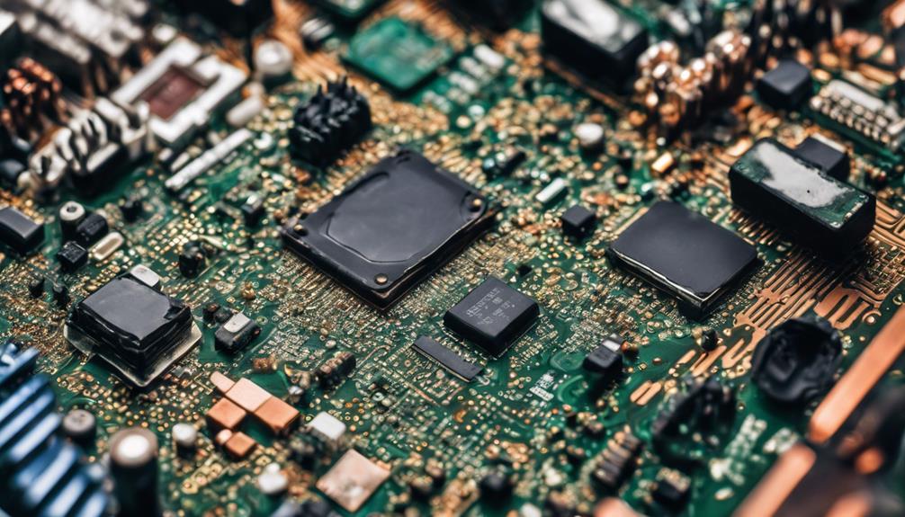
Improper SMT component placement can lead to a multitude of defects, from functionality issues and shorts to soldering defects and weakened electrical connections.
One common error is incorrect component rotation, which can cause functionality issues and potential shorts. Misaligned components can also lead to soldering defects and weaken electrical connections, compromising the overall reliability of the assembly.
Inconsistent spacing between components can result in signal interference and affect circuit performance. Additionally, placing components too close to board edges can impact assembly reliability and lead to mechanical stress.
Moreover, overlooking component height restrictions can cause interference with neighboring components or enclosure fitment, leading to design flaws. These mistakes can be detrimental to the overall quality and reliability of the final product.
How Can Component Placement Impact the Effectiveness of Sourcing Strategies for Beginners?
When starting out, beginners must understand how best component sourcing strategies can be impacted by component placement. The positioning of components can affect procurement lead times, production efficiency, and overall cost. It’s essential to consider component placement for an effective sourcing strategy from the beginning.
Best Practices for SMT Component Placement
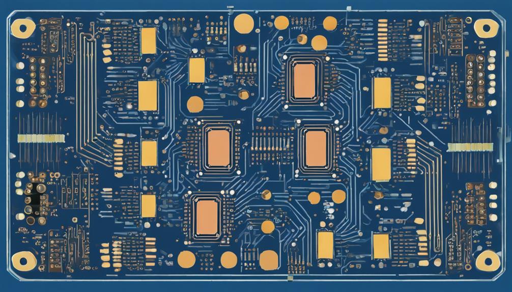
To guarantee high-quality circuit performance, reliability, and manufacturing efficiency, it is essential to adhere to rigorous component placement guidelines and manufacturer recommendations during the SMT assembly process. Proper component placement is essential for reliable circuit performance and manufacturing efficiency.
In Surface Mount Technology (SMT), accurate placement ensures peak signal integrity, thermal management, and mechanical stability.
To achieve successful SMT assembly, follow these best practices:
- Adhere to design guidelines and manufacturer recommendations to ensure efficient component placement and soldering.
- Implement automated placement machines to enhance speed and precision in component placement.
- Conduct thorough inspection processes post-placement to ensure quality control and adherence to tolerances, preventing defects and rework.
Frequently Asked Questions
What Is SMT Component Placement?
SMT component placement is the precise positioning of surface mount components on a printed circuit board (PCB) during the assembly process. This vital step guarantees the proper electrical connections and functionality of the circuit board.
Guided by the PCB design layout, accurate placement is essential for achieving high manufacturing yields and reliable electronic products.
Where Should Components Be Placed on a Pcb?
As the conductor orchestrates the harmony of electronic components, strategic placement on the PCB is paramount. Components should be situated to minimize signal interference, optimize thermal management, and facilitate efficient assembly.
Critical components, such as ICs and connectors, should be positioned to guarantee seamless signal flow and maximize board functionality. By carefully selecting component locations, designers can create a symphony of circuit performance, where every element works in harmony to achieve the best results.
What Is the First Thing to Consider When Placing Components?
When placing components, the primary consideration is to verify accurate PCB CAD footprints that match part specifications. This guarantees correct pad sizes and locations, preventing weak solder joints and potential short circuits.
When Planning Component Placement in a PCB Layout Which Components Are Recommended to Be Placed First?
When planning component placement in a PCB layout, it is recommended to prioritize components with fixed locations, such as connectors and switches, to establish critical board dimensions. This sets the foundation for the overall layout, ensuring efficient use of space and minimizing potential design flaws.
