To begin creating efficient printed circuit boards, beginners require a solid foundation in PCB design software. Start with KiCad's user-friendly interface and abundant resources. Next, explore Eagle's schematic creation and routing optimization capabilities. Fritzing's open-source software and breadboard view provide a unique design experience. Orcad's extensive libraries and simulation tools offer advanced features. Altium Designer's rules-driven design and community engagement create a versatile platform. Proteus PCB Design's holistic solution and virtual simulation guarantee accuracy. Diptrace's real-time 3D preview and multi-layer support simplify design. Easyeda's integrated design process and real-time collaboration provide limitless possibilities. Finally, PADS' precision design and automation features streamline the process. Continue exploring these essential tutorials to master PCB design and access advanced capabilities.
Key Takeaways
- KiCad and Fritzing tutorials are ideal for beginners due to their user-friendly interfaces and abundant resources.
- Eagle tutorials provide a comprehensive introduction to PCB design, covering schematic creation, component selection, and routing optimization.
- Proteus PCB Design software tutorials offer a holistic solution, integrating tool integration, virtual simulation, and accuracy in layout considerations.
- Diptrace tutorials focus on real-time 3D preview, multi-layer PCB support, and user-friendly interface for schematic capture and layout.
- Tutorials on Easyeda, Altium Designer, and PADS provide a comprehensive understanding of PCB design, from basics to advanced techniques.
Getting Started With Kicad
With KiCad's user-friendly interface and abundant resources, beginners can quickly immerse themselves in the world of PCB design, utilizing its extensive features to bring their projects to life. This open-source software offers a complete design experience, encompassing schematic capture, PCB layout, and 3D viewer features.
Moreover, KiCad's cross-platform compatibility guarantees seamless operation on Windows, macOS, and Linux operating systems.
One of the primary advantages of KiCad is its vast library of components and resources, catering to diverse project requirements. This extensive repository enables users to find and utilize pre-designed components, greatly reducing design time and effort.
Additionally, KiCad's active community provides an array of tutorials, forums, and resources, empowering beginners to enhance their PCB design skills. By leveraging KiCad's features and resources, beginners can efficiently create complex PCB designs, paving the way for innovative and successful projects.
Eagle Tutorial for Beginners
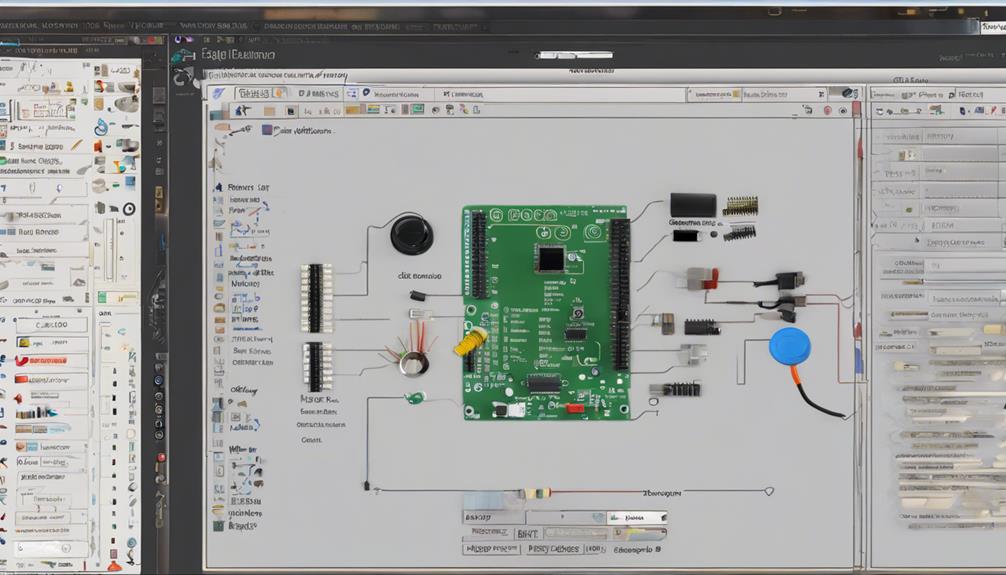
In this Eagle tutorial for beginners, we will explore the fundamental steps required to create a printed circuit board (PCB) design.
The process begins with setting up Eagle, followed by creating a schematic, and finally, designing the board.
Setting Up Eagle
To initiate the Eagle design process, a new project must be created by specifying a project name, directory, and project type. This sets the foundation for a successful PCB layout.
In Eagle, the interface operates on a modal system, providing efficient views such as Library, Schematic, Board, and Control Panel. When creating a project, it is crucial to select the correct project type, as this determines the design rules and settings for the project.
Upon project creation, the focus shifts to component selection, where resistors, capacitors, and other components are added to the schematic. Strategic part placement and routing optimization are critical considerations when progressing from the schematic to PCB layout.
Implementing ground planes and efficient routing techniques are key to achieving a well-designed PCB layout. By following these steps, designers can set up Eagle effectively, paving the way for a successful PCB design.
With Eagle's user-friendly interface and availability for download online, beginners can quickly get started with their PCB design journey.
Creating a Schematic
Creating a schematic in Eagle is an essential step in the PCB design process, as it provides a visual representation of the circuit and enables designers to verify the correctness of their design before proceeding to the layout stage.
To begin, create a new project and add a schematic to initiate the design process. Populate the schematic with components such as resistors, capacitors, and LEDs to represent the circuit. Use the net command to connect components and label nets for clear signal flow. Assign values to components based on circuit requirements for accurate simulation and analysis.
Familiarize yourself with Eagle's modal interface, which includes key views like Library, Schematic, Board, and Control Panel, to navigate the design efficiently.
Designing the Board
With your schematic complete, you can now move on to the board design stage, where you'll strategically place components and optimize your PCB layout in Eagle.
In this vital stage, you'll transform your 2D schematic into a 3D board design. To begin, create a new board by selecting 'File' > 'Switch to Board' or by using the shortcut key 'Ctrl + Shift + B'. This will open the board editor, where you can start placing components.
Optimize your board layout by strategically placing parts and utilizing commands like Mirror and Rotate to guarantee efficient use of space. Implementing ground planes in Eagle will also streamline your PCB design process.
As you place components, use the 'Move' and 'Drag' tools to adjust their positions. Finally, finalize your PCB design by routing parts, performing Design Rule Checks (DRC), and enhancing component visibility.
PCB Design Basics With Fritzing

Fritzing, an open-source software, provides an ideal platform for beginners to learn and master the fundamentals of PCB design. Its user-friendly interface, featuring drag-and-drop functionality, enables effortless schematic creation. The software's breadboard view allows users to simulate circuit connections before proceeding to PCB layout, guaranteeing a thorough understanding of the design.
Fritzing's design capabilities extend to custom PCB layouts, which can be exported as fabrication-ready files. This versatility makes it an ideal tool for hobbyists, educators, and beginners entering the world of PCB design.
A critical aspect of PCB design is the Design Rule Check (DRC), which validates that the design meets the manufacturer's requirements. Fritzing's DRC capabilities enable users to identify and rectify potential design flaws, resulting in a more reliable and efficient design process.
Creating a Schematic With Orcad
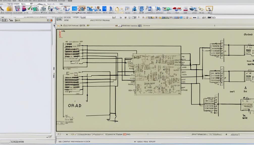
OrCAD's schematic capture capabilities enable users to effectively translate design concepts into functional electronic circuits through the creation of accurate and detailed schematics. This is achieved by adding components from OrCAD's extensive libraries, connecting nets to define circuit connections, and defining properties to specify component attributes. The intuitive interface allows for easy navigation and editing of schematic designs, streamlining the design process.
As users create their schematic, OrCAD's simulation and analysis tools can be utilized to verify and optimize the design. This validates that the final PCB board design meets the desired specifications and performance requirements.
With OrCAD, users can create complex schematic designs with ease, leveraging the software's powerful features to bring their design concepts to life. By mastering OrCAD's schematic capture capabilities, designers can efficiently create accurate and functional electronic circuits, ultimately resulting in a well-designed PCB board that meets the project requirements.
PCB Layout Essentials With Altium
What sets Altium Designer apart from other PCB design software is its rules-driven design engine, which facilitates efficient and error-free PCB layout. This feature guarantees that circuit boards are designed with precision and accuracy, minimizing the risk of errors and defects.
With Altium Designer, users have access to a versatile platform for designing and manufacturing high-quality circuit boards.
To get started with PCB layout, beginners can take advantage of Altium's resources, including:
- Altium Academy, which offers tutorial videos on PCB layout techniques
- AltiumLive forum, where users can engage in discussions and gain industry insights
- A component management system, providing easy access to millions of parts
Designing With Proteus Software
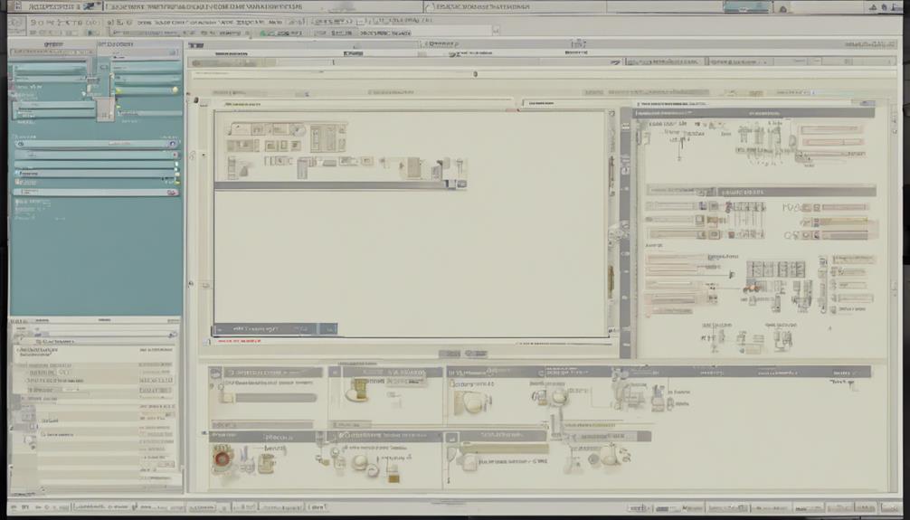
When designing with Proteus software, a solid understanding of PCB design basics is essential.
This includes knowledge of layout considerations, component placement, and routing techniques.
PCB Design Basics
In the field of printed circuit board (PCB) design, Proteus software stands out as a holistic solution, offering a seamless integration of schematic capture and layout tools that enable users to efficiently design and validate their PCB layouts.
When designing a circuit, Proteus software allows users to simulate and test their designs virtually before fabrication, reducing the risk of errors and minimizing the need for costly revisions. This guarantees that the final PCB layout is accurate and functional.
Some key benefits of using Proteus software for PCB design basics include:
- Efficient circuit design and validation: Proteus software enables users to design and validate their circuits quickly and accurately, reducing the risk of errors and ensuring that the final PCB layout meets the required specifications.
- Seamless integration with microcontrollers: Proteus software integrates with popular microcontroller models, making it an ideal solution for embedded system design.
- User-friendly interface: Proteus software provides a user-friendly interface that makes it easy for beginners to learn PCB design basics and start designing their own circuits.
Proteus Software Tools
In addition, all-encompassing Proteus Software enables designers to efficiently navigate the entire PCB design process, from schematic capture to simulation and PCB layout.
This extensive suite allows designers to create and edit schematics, simulate circuit behavior, and layout printed circuit boards with ease. Proteus supports various microcontroller models, making it an ideal choice for embedded system design.
One of the key features of Proteus is its virtual prototyping capability, which enables designers to test and debug their designs before moving to hardware implementation. This reduces the risk of errors and saves time and resources.
Proteus also offers real-time simulation capabilities, allowing for accurate circuit analysis and optimization. Additionally, the software facilitates seamless integration of schematic and PCB design, enabling efficient project development and minimizing errors.
PCB Design Fundamentals With Diptrace
DipTrace, a popular and user-friendly PCB design software, provides an ideal platform for beginners to learn and master the fundamentals of PCB design. With its intuitive interface and robust features, DipTrace enables users to create intricate PCB designs with ease.
When it comes to PCB design fundamentals, DipTrace offers a wide range of tools for schematic capture, PCB layout, and component creation. The software supports multi-sheet and multi-level hierarchical schematics, allowing for a high degree of complexity and organization.
Some of the key benefits of using DipTrace for PCB design include:
- Real-time 3D PCB preview for visualizing the design
- Support for multi-layer PCBs and complex board layouts
- User-friendly interface with a gentle learning curve
Using EAGLE for PCB Creation

EAGLE, a widely adopted PCB design software, offers a user-friendly interface and accessible online resources, making it an ideal platform for beginners and experienced designers alike to create complex PCB designs with ease.
To get started, initiate a new project by naming it and adding schematics. Then, add parts such as resistors and capacitors, and connect them using the net command. Once the schematic is complete, move to the Board view for layout creation. Strategic part placement is vital, and commands like Mirror and Rotate facilitate layout optimization. Implementing ground planes and routing parts efficiently are also essential for a well-designed layout.
Finalizing the PCB design involves conducting a Design Rule Check (DRC) to ensure manufacturability, enhancing component visibility, and exploring PCB fabrication options for production.
EAGLE's modal interface, comprising Library, Schematic, Board, and Control Panel views, streamlines the design process. By mastering EAGLE's features, designers can create complex PCBs with ease, making it an ideal choice for beginners and experienced designers alike.
PCB Design Tutorial With Easyeda

Easyeda's user-friendly web-based interface allows designers to seamlessly access a wide range of PCB design tools, including schematic capture, PCB layout, and circuit simulation, without the need for software installation. This accessibility enables designers to focus on creating innovative PCB designs without worrying about software setup.
With Easyeda, designers can efficiently design a board from scratch, leveraging the platform's extensive component library for easy part selection and placement. The platform's collaborative capabilities also enable seamless sharing and working on PCB projects with others.
Key benefits of using Easyeda include:
- Integrated design process: Access a complete set of PCB design tools in a single web-based platform.
- Real-time collaboration: Share and work on PCB projects with others in real-time, facilitating efficient teamwork and feedback.
- Limitless design possibilities: Leverage Easyeda's vast component library and advanced simulation capabilities to bring your PCB design visions to life.
Mastering PCB Design With PADS

Mastering PCB design with PADS requires a solid understanding of the software's fundamentals and advanced features. In this section, we will explore the PADS basics tutorial, covering the essential skills and techniques necessary for designing with precision.
PADS Basics Tutorial
PADS' intuitive interface and advanced features make it an ideal platform for beginners to master the fundamentals of PCB design. With its extensive toolset, PADS enables users to create professional-quality circuit boards from scratch.
The PADS Basics Tutorial takes beginners through essential tasks, including creating schematics, placing components, and routing traces. This hands-on approach helps learners develop a solid understanding of PCB design principles.
By mastering PADS, beginners can:
- Implement design rules to guarantee error-free layouts
- Utilize interactive routing for efficient trace placement
- Perform design rule checks (DRC) to identify potential issues
Designing With Precision
By harnessing PADS' advanced design automation features and extensive component libraries, designers can create intricate PCB designs with precision and accuracy, ensuring peak performance and reliability. This precision is achieved through PADS' intuitive interface, which streamlines the design process and facilitates the creation of intricate layouts.
PADS' robust design capabilities enable users to fine-tune their designs, ensuring ideal signal integrity and thermal management. The software's extensive component libraries provide access to a wide range of components, allowing designers to select the perfect parts for their specific design requirements.
As designers navigate the design process, PADS' advanced analysis tools enable them to simulate and analyze their designs, identifying potential issues and optimizing performance. With PADS, designers can confidently create complex PCB designs, knowing that their creations will meet the highest standards of precision and reliability.
Frequently Asked Questions
How to Learn PCB Design for Beginners?
To learn PCB design as a beginner, start by grasping fundamental concepts and terminology.
Familiarize yourself with beginner-friendly software tutorials and resources, and practice schematic and layout design using step-by-step guides.
Engage with online communities and forums for support and additional learning.
Apply your knowledge by experimenting with simple projects, gradually building your skills and confidence.
Where Can I Learn PCB Design for Free?
To acquire PCB design skills without incurring costs, leverage free online resources. YouTube tutorials and forums provide a solid foundation in PCB design basics.
Utilize free software like Eagle, KiCad, or DipTrace for hands-on practice. Online communities and forums offer support and guidance, while free webinars and workshops provide specialized knowledge.
Additionally, take advantage of free courses and tutorials offered by universities or online platforms for structured learning.
What Software Do PCB Designers Use?
PCB designers rely on various software tools to facilitate their design process. Industry-standard options include Altium Designer, known for its advanced features and high-speed design solutions.
Eagle is another popular choice, offering a user-friendly interface and smooth schematic-to-PCB conversion.
KiCad, an open-source solution, boasts a strong community support system, while DipTrace provides an intuitive interface and 3D modeling capabilities.
These software options cater to designers of varying expertise, from beginners to seasoned professionals.
How Hard Is Altium to Learn?
Mastering Altium requires a gentle learning curve, as the software is designed to facilitate intuitive design. With a user-friendly interface and rules-driven design engine, beginners can easily navigate the platform.
The extensive resources, including Altium Academy tutorials and community support, provide a thorough learning experience.
As users progress, they'll discover the software's nuances, and with dedication, they'll harness its full potential, transforming their PCB design skills.
