Circuit simulation is a powerful tool for electronic engineers and hobbyists, allowing for virtual design, testing, and prototyping of circuits before physical implementation. To get started, choose a suitable simulation tool, such as LTSpice or KiCad, considering circuit complexity and design tools. Set up your first circuit by selecting and adding components, connecting them with wires, and configuring the simulation type. Understand circuit components, including voltage sources, resistors, and capacitors, and learn basic circuit analysis techniques, such as Ohm's Law and Kirchhoff's Laws. From here, you can explore advanced simulation techniques and PCB design software, and uncover the full potential of circuit simulation for your projects.
Key Takeaways
- Choose a circuit simulation tool (e.g., LTSpice, KiCad, Falstad) based on circuit complexity, analysis level, and design tools.
- Select and add components from the toolbox, then connect them with wires to create a clear circuit diagram.
- Configure the simulation type for analysis, then bring the circuit to life using simulation software.
- Understand basic circuit components, including voltage sources, resistors, and capacitors, and their roles in circuit behavior.
- Familiarize yourself with basic circuit analysis techniques, including Ohm's Law, Kirchhoff's Laws, and node/mesh analysis methods.
Choosing the Right Simulation Tool
Among the plethora of circuit simulation tools available, selecting the right one is crucial for effective circuit design and analysis. For beginners, popular choices include LTSpice, KiCad, and Falstad.
LTSpice is widely preferred by users due to its advanced simulation capabilities, making it an ideal choice for complex circuit simulations.
KiCad, on the other hand, provides simulation features alongside powerful design tools for circuit analysis and PCB layout, making it a versatile option for designers.
Falstad, a user-friendly Java applet, is suitable for basic circuit simulations and is an excellent choice for those new to circuit simulation.
Additionally, exploring online options like CircuitLab and Falstad's circuit simulator can aid in learning circuit simulation concepts.
When choosing a simulation tool, consider the complexity of your circuit, the level of analysis required, and the design tools needed for PCB layout. By selecting the right tool, you can ensure accurate simulations, efficient design, and effective analysis.
Setting Up Your First Circuit
With your chosen simulation tool in place, the next step is to build and set up your first circuit, an essential process that lays the foundation for effective analysis and design. This is where you'll bring your circuit to life using the circuit simulation software.
To set up your first circuit, follow these essential steps:
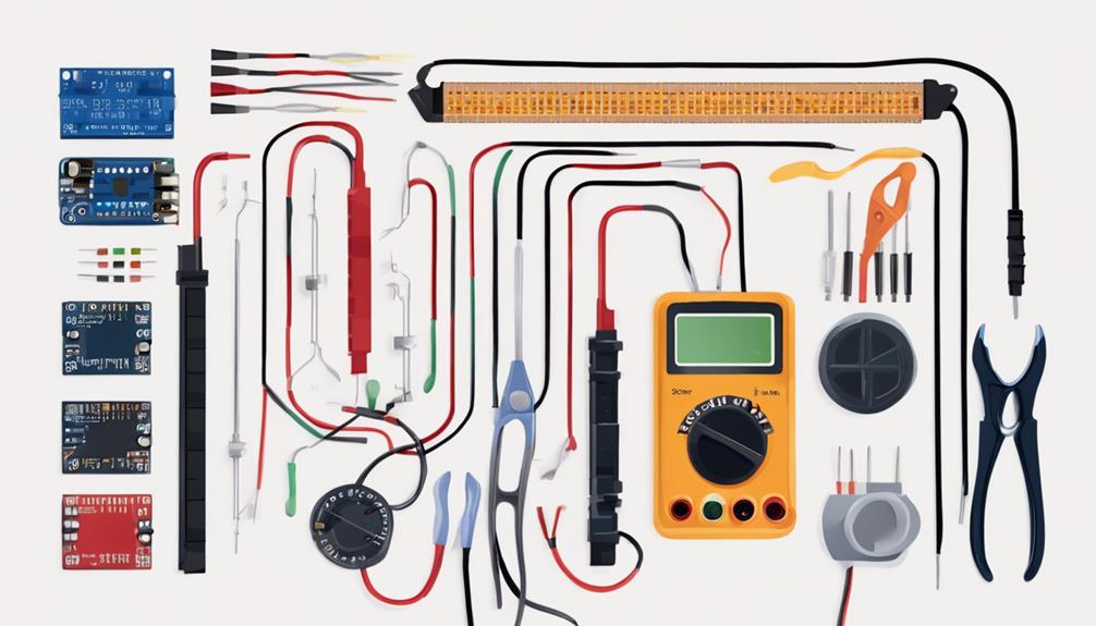
- Select and add components: Choose components like resistors and capacitors from the toolbox and add them to your circuit diagram.
- Connect components with wires: Drag wires from one terminal to another to connect your components, ensuring a clear and accurate circuit diagram.
- Configure the simulation: Set up the simulation type, such as DC analysis or AC analysis, to analyze circuit behavior and execute the simulation.
Understanding Circuit Components

As we explore the domain of circuit simulation, it is essential to grasp the fundamental components that comprise a circuit.
In this section, we will examine the core components that facilitate the flow of electrical energy, including voltage sources, resistors, and capacitors, which form the backbone of any electrical circuit.
Voltage Sources Explained
In a circuit, voltage sources are important components that provide a stable voltage output, maintaining a consistent level regardless of the current flowing through them. These components are critical for powering electronic devices and determining the overall behavior of a circuit. Voltage sources can be represented by symbols like a battery or a DC power supply in circuit diagrams.
To effectively design and analyze circuits, it is imperative to understand the role of voltage sources. Here are three key aspects of voltage sources:
- Constant Voltage Output: Voltage sources provide a consistent voltage level, unaffected by changes in current.
- Stable Power Supply: They ensure a reliable power supply, enabling electronic devices to function correctly.
- Circuit Behavior: Voltage sources play a critical role in determining the overall behavior of a circuit, making them a fundamental component in circuit simulation software.
When using circuit simulation software, understanding voltage sources is crucial for accurate simulations and effective circuit design. By grasping the principles of voltage sources, beginners can create more efficient and reliable circuits, paving the way for more complex and sophisticated designs.
Resistors and Their Roles
Having explored the fundamental role of voltage sources in circuits, we now turn our attention to another essential component: resistors, which play a critical role in controlling the flow of electric current and dissipating energy in the form of heat.
As passive components, resistors limit the flow of current, and their resistance value, measured in ohms (Ω), determines how much they resist current flow. Resistors are important in voltage division, current limiting, signal attenuation, and biasing circuits. With various types, including carbon film, metal film, wirewound, and variable resistors, each has specific applications.
Understanding resistor color codes is essential for quickly identifying the resistance value and tolerance of a resistor. When using circuit simulation software, accurately modeling resistors is crucial for precise circuit behavior predictions.
Capacitors in Circuits
Capacitors, a fundamental component in electronic circuits, possess the unique ability to store and release electrical energy, thereby influencing the flow of current and voltage. This property makes them essential in a wide range of applications, from filtering and coupling to timing and energy storage.
When using circuit simulation software, it's important to comprehend the behavior of capacitors in various circuit configurations. Here are three key aspects to take into account:
- Blocking DC, Allowing AC: Capacitors block direct current (DC) while allowing alternating current (AC) to pass through, making them ideal for filtering and signal processing applications.
- Capacitance Value: The capacitance value determines how much charge a capacitor can store per unit of voltage, affecting its ability to influence the circuit's behavior.
- Series and Parallel Connections: Capacitors can be connected in series or parallel to alter the overall capacitance in a circuit, enabling designers to tailor the circuit's response to specific requirements.
Basic Circuit Analysis Techniques
In circuit analysis, it is essential to understand the fundamental laws governing voltage and current, including Ohm's Law and Kirchhoff's Laws.
Building upon these principles, node analysis and mesh analysis methods provide systematic approaches to solving complex circuits.
Voltage and Current Laws
When analyzing electronic circuits, understanding the fundamental relationships between voltage, current, and resistance is essential, and this is where Ohm's Law and Kirchhoff's Laws come into play. These fundamental laws form the foundation of circuit analysis, enabling the prediction and troubleshooting of circuit behavior.
To master circuit simulation using simulation software, it's important to grasp these laws:
- Ohm's Law: Relates voltage, current, and resistance as V = I \* R, providing a fundamental understanding of circuit operation.
- Kirchhoff's Voltage Law: States that the sum of voltages around a closed loop is zero, ensuring that voltage sources and drops are balanced.
- Kirchhoff's Current Law: States that the sum of currents entering a node equals the sum of currents leaving the node, ensuring current continuity.
Node Analysis Method
By applying Kirchhoff's Laws to individual nodes, node analysis provides a systematic approach to determining node voltages in a circuit, enabling the analysis of complex circuits. This fundamental technique involves applying Kirchhoff's Current Law (KCL) at each node to establish equations for the unknown node voltages. Node analysis simplifies complex circuits by breaking them down into individual nodes and analyzing their relationships.
| Node | Voltage | Current |
|---|---|---|
| Node 1 | V1 | I1 |
| Node 2 | V2 | I2 |
| Node 3 | V3 | I3 |
The number of equations required for node analysis is equal to the number of nodes minus one. This technique is essential for understanding circuit behavior and designing efficient electronic systems. By using node analysis, circuit designers and engineers can accurately predict the behavior of complex circuits, making it an indispensable tool in the development of modern electronic systems. In conjunction with circuit simulation software, node analysis enables the rapid prototyping and testing of circuit designs, streamlining the development process and reducing the risk of errors.
Mesh Analysis Method
Mesh analysis, a fundamental technique in circuit analysis, involves the application of Kirchhoff's Voltage Law to determine the mesh currents in a circuit. This method is particularly useful for circuits with multiple loops and interconnected components.
By creating mesh equations for each closed loop in the circuit, mesh analysis simplifies complex circuits by breaking them down into manageable equations for solving.
The benefits of mesh analysis include:
- Efficient problem-solving: Mesh analysis allows beginners to solve circuit problems systematically and efficiently.
- Simplified circuit analysis: By breaking down complex circuits into manageable equations, mesh analysis makes it easier to analyze and understand circuit behavior.
- Improved accuracy: Mesh analysis maintains accuracy in circuit analysis, making it an essential technique in circuit simulation software.
Creating a Circuit Schematic

In the process of creating a circuit schematic, selecting the necessary components from the toolbox is the crucial first step. This is where the circuit simulation software provides an extensive library of components, including resistors, capacitors, transistors, and more. By selecting the required components, you can begin building your circuit schematic.
Next, place the chosen components on the schematic canvas in a clear and organized layout. This is essential for maintaining clarity in the design and ensuring accurate simulation results. Connect the components using wires to establish the necessary electrical connections for the circuit. Proper labeling of components and wires is also vital to maintain clarity in the schematic design.
A well-structured and accurately connected circuit schematic is vital for successful simulation and analysis. By following these steps, you can create a reliable circuit schematic that sets the foundation for effective circuit simulation and analysis.
With a well-designed circuit schematic, you can confidently proceed to the next step in the circuit simulation process, leveraging the capabilities of your circuit simulation software.
Running Your First Simulation

With a well-designed circuit schematic in place, it is now possible to proceed with running your first simulation, an essential step in analyzing the behavior and performance of your circuit. This is where you get to see your circuit in action, and simulation software makes it all possible.
To run your first simulation, follow these essential steps:
- Select a simulation type: Choose the type of simulation that aligns with the behavior you want to analyze, such as DC, AC, or Transient analysis.
- Set up simulation parameters: Define voltage sources, component values, and analysis settings to guarantee accurate results.
- Execute the simulation: Run the simulation to observe how your circuit responds to the input signals.
Interpreting Simulation Results
When interpreting simulation results, it is essential to accurately read waveforms and analyze simulation data to gain insight into circuit behavior. This involves identifying key features, such as voltage and current waveforms, and extracting meaningful information from the data.
Reading Waveforms Correctly
Accurate interpretation of simulation results relies on a thorough understanding of the waveform plot, where voltage and time scales provide the framework for analyzing circuit behavior. A well-annotated waveform plot is essential for extracting valuable insights from simulation results.
To read waveforms correctly, it is essential to focus on the following key aspects:
- Peak values and frequency: Identify the maximum and minimum values of the waveform, as well as its frequency, to analyze the behavior of components in the circuit.
- Waveform shape and steady-state conditions: Examine the waveform shape to identify steady-state conditions, transient responses, and any anomalies that may indicate issues with the circuit design.
- Amplitude, frequency, and phase shift: Pay attention to the amplitude, frequency, and phase shift of signals to troubleshoot circuit performance and validate design assumptions.
Analyzing Simulation Data
Simulation results are typically presented in the form of graphs and plots, which provide a visual representation of the circuit's behavior, enabling engineers to extract valuable insights and validate their design assumptions.
When analyzing simulation data, it is essential to focus on key parameters such as voltage, current, power, and frequency. By comparing expected values with simulation results, engineers can validate the accuracy of their circuit design and identify areas for improvement.
Understanding how changes in component values impact the simulation output is vital for optimizing circuit performance. Moreover, simulation data can be used to troubleshoot circuit issues and refine the design for desired functionality.
Effective analysis of simulation data is critical in circuit simulations, as it enables engineers to make informed design decisions and ensure that their circuits meet the required specifications.
Common Simulation Mistakes

Inexperienced engineers and circuit designers frequently fall prey to a range of common mistakes that can greatly compromise the reliability of their simulation results. These mistakes can lead to inaccurate and unreliable data, ultimately affecting the performance of the designed circuit. To avoid such pitfalls, it is essential to be aware of these common simulation mistakes.
The following mistakes can have a substantial impact on the accuracy of simulation results:
- Incorrect component values: Failing to verify component values can lead to inaccurate simulation results.
- Wiring errors: Incorrect wiring connections can cause unexpected behavior in the simulation, resulting in unreliable data.
- Neglecting convergence issues: Ignoring simulation convergence issues may result in unreliable data, compromising the integrity of the simulation.
Advanced Circuit Simulation Techniques

Employing advanced circuit simulation techniques enables designers to harness the capabilities of specialized software, facilitating the creation of highly accurate models that closely mirror real-world circuit behavior. This is achieved by utilizing software such as LTSpice XVII, which allows users to import actual component models, ensuring precise simulations.
Commercial circuit simulators offer advanced features and accurate simulation results, making them ideal for experienced users. Systemvision is another powerful tool, providing capabilities for complex projects and advanced circuit simulations.
In contrast, Everycircuit is geared towards beginners, offering circuit animation and interactive features. EasyEDA, on the other hand, focuses on powerful simulation and PCB designing, making it suitable for both beginners and advanced users.
Working With PCB Design Software

PCB design software, such as KiCad, has become an indispensable tool for electronic engineers, allowing them to transform circuit schematics into physical board layouts with precision and accuracy. These software tools play a crucial role in the circuit design process, enabling users to create professional-grade circuit board layouts. By leveraging PCB design software, engineers can efficiently translate circuit schematics into physical board layouts, ready for manufacturing.
The benefits of using PCB design software include:
- Component placement and routing: Accurately place components and route connections to ensure peak board performance.
- Design rule checking: Identify potential design flaws and errors, ensuring adherence to manufacturing requirements.
- Virtual simulation and testing: Simulate and test PCB designs virtually, reducing the need for physical prototypes and accelerating the design process.
Troubleshooting Circuit Simulation Issues

When simulating a circuit, it is not uncommon for issues to arise, and identifying the root cause of these problems can be a time-consuming and frustrating process.
To troubleshoot circuit simulation issues, it is essential to follow a systematic approach to identify and rectify the problem. First, verify the circuit schematic by checking for proper component connections and orientation.
Next, review the simulation settings, including the simulation type, parameters, and analysis options, to make sure they are correctly configured. Component values, models, and properties should also be scrutinized for any errors that could affect simulation results.
It is important to confirm that the circuit simulation software is updated to the latest version to avoid any software-related issues. Finally, carefully review the simulation output and compare it with expected results to pinpoint discrepancies.
Best Practices for Circuit Simulation

What distinguishes a successful circuit simulation from a failed one is often the attention to detail in setting up the simulation, from selecting the right components to configuring the analysis parameters. To guarantee accurate and reliable results, it is essential to follow best practices in circuit simulation.
Here are three key best practices to keep in mind:
- Accurate Component Selection: Confirm that component values and models accurately represent the physical components used in the circuit.
- Proper Analysis Configuration: Adjust analysis parameters, such as simulation time, frequency range, and solver settings, to match the specific requirements of the circuit design.
- Clear and Organized Diagrams: Develop clear and organized circuit diagrams to facilitate efficient simulation setup and result interpretation.
Taking Your Simulation Skills Further

To enhance your circuit simulation skills and tackle complex designs and optimize performance, it is crucial to explore advanced features in circuit simulation software. Dive into different simulation types, such as transient analysis, frequency response, and noise analysis, to gain a deeper understanding of circuit behavior.
Utilize specialized tools for PCB design integration to enhance your circuit projects and streamline your workflow.
To optimize circuit performance, learn how to analyze and interpret simulation results effectively. This will enable you to identify areas for improvement and make data-driven design decisions.
Engage with online communities and forums to seek advice and share insights on advanced simulation techniques. By doing so, you'll stay up-to-date with the latest trends and best practices in circuit simulation.
Frequently Asked Questions
How to Create a Circuit Simulation?
To create a circuit simulation, you first need to select suitable software such as LTSpice or Qucs Studio. Initiate a new project within the software.
Construct a circuit diagram by adding various components such as resistors, capacitors, transistors, and others. Connect these components together using wires to form a complete circuit.
Configure the simulation by specifying the type of analysis you want to perform (DC, AC, Transient) and adjust the parameters accordingly for the analysis to be conducted accurately.
What Is the Basic of Circuit Simulation?
The foundation of circuit simulation lies in the mathematical modeling of electronic circuits. It involves representing physical components and their interactions using equivalent circuits, which are then analyzed using numerical methods.
This allows for the prediction of circuit behavior, including voltage, current, and power distributions. By solving the underlying equations, circuit simulators provide a virtual environment to test, analyze, and optimize circuit designs, enabling users to gain valuable insights and refine their designs.
What Is the Most Widely Used Circuit Simulator?
Imagine exploring a virtual electronics laboratory, where circuits come alive with a click. Among the myriad of circuit simulators, one stands tall: LTspice.
Widely regarded as the most popular circuit simulator, LTspice offers an intuitive interface, extensive component library, and accurate simulations. Its compatibility with Windows and Linux, along with free availability, makes it a go-to choice for engineers and hobbyists alike, solidifying its position as the industry's gold standard.
How to Run Simulation on Circuit Lab?
To run a simulation on Circuit Lab, follow these steps:
- Navigate to the desired circuit design and click the 'Simulate' button.
- Select the desired simulation type, such as AC or DC analysis, and specify the frequency or voltage range.
- Adjust simulation settings as needed.
- Click 'Run' to initiate the simulation.
Real-time results will be displayed, allowing for in-depth analysis of circuit behavior.